Photo by Jakub Zerdzicki on Pexels
Tolerance Stackup in 3D Printed Assemblies

Tolerance Stackup in 3D Printed Assemblies
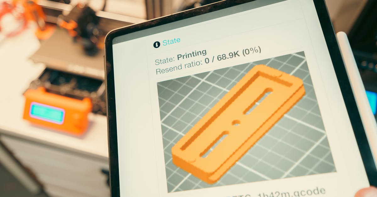
When designing assemblies with multiple 3D printed parts, understanding tolerance stackup can mean the difference between parts that fit perfectly and expensive reprints. Whether you’re prototyping a complex mechanism or producing small batches of multi-part products, managing tolerances effectively saves time, material, and frustration.
At CLT 3D Printing, we work with businesses across Charlotte to ensure their assemblies come together correctly the first time. This guide breaks down the critical concepts of tolerance stackup in FDM 3D printing and provides practical strategies for designing assemblies that work.
What Is Tolerance Stackup and Why Does It Matter?
Tolerance stackup refers to the cumulative effect of individual part tolerances in an assembly. When you combine multiple parts, each with its own dimensional variation, these small differences can add up to create significant fit issues. In traditional manufacturing, this concept is well-established, but 3D printing introduces unique considerations.
FDM 3D printing typically achieves tolerances of ±0.2mm to ±0.5mm depending on the printer, material, and part geometry. While this might seem minor for a single part, imagine an assembly with five interlocking components - suddenly you’re dealing with potential variations of up to 2.5mm in the worst case.
The challenge becomes even more complex when mixing 3D printed parts with off-the-shelf components that have tighter tolerances. A bearing that needs a precise press fit or a threaded insert requiring specific clearance demands careful planning in your 3D printed housing.
Common Tolerance Challenges in 3D Printed Assemblies
Thermal expansion and contraction create dimensional changes that vary by material. PLA has minimal shrinkage (0.2-0.5%), while ABS can shrink 0.8-3% as it cools. PETG falls in between at 0.5-0.8%. These percentages might seem small, but on a 100mm part printed in ABS, you could see up to 3mm of dimensional change.
Layer adhesion and print orientation also affect tolerances. Dimensions in the Z-axis (vertical) tend to be more accurate than X-Y dimensions due to the fixed layer height. However, features printed parallel to the build plate often have better surface finish and tighter tolerances than those requiring support material.
Photo by Jakub Zerdzicki on Pexels
First-layer compression adds another variable. The initial layer often spreads slightly wider than subsequent layers to ensure bed adhesion, creating what’s known as “elephant’s foot.” This effect can throw off critical mating surfaces if not accounted for in the design phase.
Design Strategies for Managing Stackup
Start with a tolerance budget for your entire assembly. List each mating interface and assign realistic tolerances based on the criticality of the fit. For example, a decorative housing might accept ±0.5mm variations, while a bearing seat needs ±0.1mm precision.
Consider using locating features to control stackup. Pins, slots, and datum surfaces help ensure parts align correctly regardless of minor dimensional variations. Design these features to be slightly oversized on one part and undersized on the mating part - typically 0.1-0.2mm clearance for FDM printing.
Break complex assemblies into sub-assemblies when possible. This approach limits the number of tolerances that stack up in any single direction. It also makes troubleshooting easier if fit issues arise.
Material Selection Impact on Tolerances
Material properties directly influence achievable tolerances and long-term dimensional stability. PLA offers excellent dimensional accuracy for prototypes and indoor applications, maintaining tight tolerances when kept below 60°C. Its low shrinkage rate makes it predictable for multi-part assemblies.
PETG provides a balance of accuracy and durability. While it has slightly more shrinkage than PLA, its superior chemical resistance and temperature tolerance (up to 80°C) make it ideal for functional assemblies that need to maintain tolerances in varying conditions.
For assemblies requiring tight tolerances and heat resistance, consider post-processing options. Annealing PETG parts can relieve internal stresses and improve dimensional stability, though it requires careful control to avoid warping.
Practical Testing Methods
Always prototype critical interfaces before committing to full production. Print small test sections of mating features to verify fit without using material on complete parts. A simple 20mm x 20mm test piece with your specific interface geometry can save hours of troubleshooting.
Use go/no-go gauges for repetitive features. 3D print gauge blocks that represent the maximum and minimum acceptable dimensions for critical features. This approach provides quick pass/fail verification during production runs.
Document your findings in a tolerance table specific to your printer and materials. Track actual vs. designed dimensions across different feature types - holes, posts, slots, and walls. This data becomes invaluable for future designs.
Software Compensation Techniques
Modern slicing software offers several tools to manage tolerances. Horizontal expansion settings allow you to uniformly grow or shrink the outer perimeter of parts. A setting of -0.1mm can compensate for the typical expansion seen in FDM printing, helping achieve tighter tolerances.
Hole horizontal expansion specifically adjusts internal features without affecting external dimensions. This targeted approach helps achieve proper clearance for fasteners and inserts while maintaining overall part accuracy.
Some slicers also support variable layer heights, allowing finer resolution in critical areas while using thicker layers elsewhere. This technique can improve Z-axis tolerances for specific features without significantly increasing print time.
When to Consider Alternative Approaches
Recognize when tolerance requirements exceed FDM capabilities. Features requiring tolerances tighter than ±0.1mm might need post-processing through drilling, reaming, or milling. Designing with standardized drill sizes in mind simplifies this secondary operation.
For extremely tight tolerance requirements, consider hybrid approaches. 3D print the bulk geometry and use precision inserts or bushings for critical interfaces. This method leverages the design freedom of 3D printing while achieving machined-part precision where needed.
Assemblies with many parts might benefit from selective laser sintering (SLS) or stereolithography (SLA) for specific components. While we specialize in FDM printing at CLT 3D Printing, we can advise when alternative technologies might better serve your tolerance requirements.
Real-World Application Examples
Drone and UAV assemblies demonstrate practical tolerance management. Motor mounts require precise alignment to prevent vibration, while body panels need enough clearance for easy assembly. A typical approach uses tight tolerances (±0.15mm) for motor mounting holes and looser tolerances (±0.3mm) for cosmetic panels.
Manufacturing fixtures show another application of tolerance stackup principles. A fixture holding multiple parts for assembly must account for both the tolerance of each pocket and the accumulated position tolerance across the fixture. Using a common datum surface and progressive positioning helps maintain accuracy.
Automotive replacement parts often interface with existing components having unknown tolerances. Design these parts with adjustable features or compliance zones that can accommodate variation in the mating components.
Ready to Master Assembly Tolerances?
Understanding tolerance stackup transforms multi-part 3D printed assemblies from frustrating puzzles into predictable successes. Whether you’re developing prototypes or producing small batches, proper tolerance management ensures parts fit right the first time.
At CLT 3D Printing, we help Charlotte-area businesses navigate these technical challenges. Our experience with PLA and PETG materials, combined with careful process control, delivers assemblies that meet your functional requirements.
Need help designing your next multi-part assembly? Let’s discuss your project and develop a tolerance strategy that works.
Related Resources
Related Articles
Prototype Testing Methods That Save Time
Learn proven prototype testing techniques that accelerate development cycles and catch issues before expensive production runs.
3D Printing Tolerances: What to Expect
Understanding dimensional tolerances in FDM 3D printing helps set realistic expectations for your parts.

Batch Size Economics: The 3D Printing Advantage
Learn why 3D printing dominates at 10-500 units and how to calculate your optimal production method.